

DC Motor Control using Arduino
- Mohamed Khaled

- Oct 18, 2018
- 15 min read
Updated: Oct 23, 2018
The main objective of the group task this time around was also to control the motion of a DC motor making it move forwards, backwards, and stop, like the previous task, with the aid of sensors and switches. However, in this task we were allowed to use Arduino to program our circuit. Therefore, the task was focused on controlling the motor's motion using both electronics and programming in order to further experience working with electronics and know how to integrate between both. Our group consisted of four members.
What is Arduino?
Arduino is an open-source hardware and software company, project and user community that designs and manufactures single-board microcontrollers and microcontroller kits for building digital devices and interactive objects that can sense and control objects in the physical and digital world. Its products are licensed under the GNU Lesser General Public License (LGPL) or the GNU General Public License (GPL), permitting the manufacture of Arduino boards and software distribution by anyone. Arduino boards are available commercially in preassembled form or as do-it-yourself (DIY) kits.
Arduino board designs use a variety of microprocessors and controllers. The boards are equipped with sets of digital and analog input/output (I/O) pins that may be interfaced to various expansion boards or breadboards (shields) and other circuits. The boards feature serial communications interfaces, including Universal Serial Bus (USB) on some models, which are also used for loading programs from personal computers. The microcontrollers are typically programmed using a dialect of features from the programming languages C and C++. In addition to using traditional compiler toolchains, the Arduino project provides an integrated development environment (IDE) based on the Processing language project.
The Arduino project started in 2003 as a program for students at the Interaction Design Institute Ivrea in Ivrea, Italy, aiming to provide a low-cost and easy way for novices and professionals to create devices that interact with their environment using sensors and actuators. Common examples of such devices intended for beginner hobbyists include simple robots, thermostats and motion detectors.
The name Arduino comes from a bar in Ivrea, Italy, where some of the founders of the project used to meet. The bar was named after Arduin of Ivrea, who was the margrave of the March of Ivrea and King of Italy from 1002 to 1014.
Arduino as a Hardware:
Arduino is open-source hardware. The hardware reference designs are distributed under a Creative Commons Attribution Share-Alike 2.5 license and are available on the Arduino website. Layout and production files for some versions of the hardware are also available.
Although the hardware and software designs are freely available under copy left licenses, the developers have requested the name Arduino to be exclusive to the official product and not be used for derived works without permission. The official policy document on use of the Arduino name emphasizes that the project is open to incorporating work by others into the official product. Several Arduino-compatible products commercially released have avoided the project name by using various names ending in –duino.
Most Arduino boards consist of an Atmel 8-bit AVR microcontroller (ATmega8, ATmega168, ATmega328, ATmega1280, ATmega2560) with varying amounts of flash memory, pins, and features. The 32-bit Arduino Due, based on the Atmel SAM3X8E was introduced in 2012. The boards use single or double-row pins or female headers that facilitate connections for programming and incorporation into other circuits. These may connect with add-on modules termed shields. Multiple and possibly stacked shields may be individually addressable via an I²C serial bus. Most boards include a 5 V linear regulator and a 16 MHz crystal oscillator or ceramic resonator. Some designs, such as the LilyPad, run at 8 MHz and dispense with the onboard voltage regulator due to specific form-factor restrictions.
Arduino microcontrollers are pre-programmed with a boot loader that simplifies uploading of programs to the on-chip flash memory. The default bootloader of the Arduino UNO is the optiboot bootloader. Boards are loaded with program code via a serial connection to another computer. Some serial Arduino boards contain a level shifter circuit to convert between RS-232 logic levels and transistor–transistor logic (TTL) level signals. Current Arduino boards are programmed via Universal Serial Bus (USB), implemented using USB-to-serial adapter chips such as the FTDI FT232. Some boards, such as later-model Uno boards, substitute the FTDI chip with a separate AVR chip containing USB-to-serial firmware, which is reprogrammable via its own ICSP header. Other variants, such as the Arduino Mini and the unofficial Boarduino, use a detachable USB-to-serial adapter board or cable, Bluetooth or other methods. When used with traditional microcontroller tools, instead of the Arduino IDE, standard AVR in-system programming (ISP) programming is used.

The Arduino board exposes most of the microcontroller's I/O pins for use by other circuits. The Diecimila, Duemilanove, and current Uno provide 14 digital I/O pins, six of which can produce pulse-width modulated signals, and six analog inputs, which can also be used as six digital I/O pins. These pins are on the top of the board, via female 0.1-inch (2.54 mm) headers. Several plug-in application shields are also commercially available. The Arduino Nano, and Arduino-compatible Bare Bones Board and Boarduino boards may provide male header pins on the underside of the board that can plug into solderless breadboards.
Many Arduino-compatible and Arduino-derived boards exist. Some are functionally equivalent to an Arduino and can be used interchangeably. Many enhance the basic Arduino by adding output drivers, often for use in school-level education, to simplify making buggies and small robots. Others are electrically equivalent but change the form factor, sometimes retaining compatibility with shields, sometimes not. Some variants use different processors, of varying compatibility.
Types of Arduino Boards:
The original Arduino hardware was produced by the Italian company Smart Projects. Some Arduino-branded boards have been designed by the American companies SparkFun Electronics and Adafruit Industries. As of 2016, 17 versions of the Arduino hardware have been commercially produced.
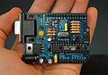
Arduino RS232 Arduino Diecimila Arduino Duemilanove (male pins) (rev 2009b)
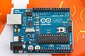
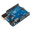
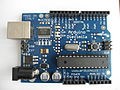
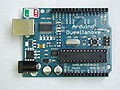
Arduino Uno R2 Arduino Uno SMD R3 Arduino Leonardo
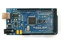
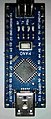
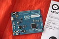
Arduino Pro Arduino Mega Arduino Nano (No USB) (DIP-30 footprint)
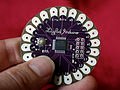
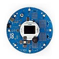
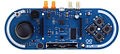
Arduino LilyPad 00 Arduino Robot Arduino Esplora
(rev 2007) (No USB)
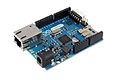
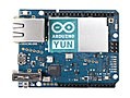
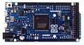
Arduino Ethernet Arduino Yun Arduino Due
(AVR + W5100) (AVR + AR9331) (ARM Cortex-M3 core)
Arduinos Shields
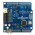
Arduino and Arduino-compatible boards use printed circuit expansion boards called shields, which plug into the normally supplied Arduino pin headers. Shields can provide motor controls for 3D printing and other applications, Global Positioning System (GPS), Ethernet, liquid crystal display (LCD), or bread boarding (prototyping). Several shields can also be made do it yourself (DIY).
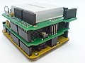
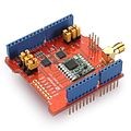
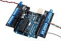
Multiple shields can be Dragino Lora Shield Screw-terminal stacked. In this example allows the user to send breakout shield in the top shield contains data and reach extremely a wing-type format a solderless breadboard. long ranges at low data-rates.
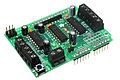
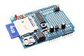
Adafruit Motor Shield with screw Adafruit Datalogging Shield with a terminals for connection to motors Secure Digital (SD) card slot and real-time clock (RTC) chip
Arduino Software

Developer(s) Arduino Software
Stable release 1.8.5 / 29 September 2017; 12 months ago Repository https://github.com/arduino/Arduino
Website www.arduino.cc/en/Main/Software
A program for Arduino hardware may be written in any programming language with compilers that produce binary machine code for the target processor. Atmel provides a development environment for their 8-bit AVR and 32-bit ARM Cortex-M based microcontrollers: AVR Studio (older) and Atmel Studio (newer).
IDE
The Arduino integrated development environment (IDE) is a cross-platform application (for Windows, macOS, Linux) that is written in the programming language Java. It originated from the IDE for the languages Processing and Wiring. It includes a code editor with features such as text cutting and pasting, searching and replacing text, automatic indenting, brace matching, and syntax highlighting, and provides simple one-click mechanisms to compile and upload programs to an Arduino board. It also contains a message area, a text console, a toolbar with buttons for common functions and a hierarchy of operation menus. The source code for the IDE is released under the GNU General Public License, version 2. The Arduino IDE supports the languages C and C++ using special rules of code structuring. The Arduino IDE supplies a software library from the Wiring project, which provides many common input and output procedures. User-written code only requires two basic functions, for starting the sketch and the main program loop, that are compiled and linked with a program stub main() into an executable cyclic executive program with the GNU toolchain, also included with the IDE distribution. The Arduino IDE employs the program avrdude to convert the executable code into a text file in hexadecimal encoding that is loaded into the Arduino board by a loader program in the board's firmware.
Sketch
A program written with the Arduino IDE is called a sketch. Sketches are saved on the development computer as text files with the file extension .ino. Arduino Software (IDE) pre-1.0 saved sketches with the extension .pde.
A minimal Arduino C/C++ program consist of only two functions:
setup(): This function is called once when a sketch starts after power-up or reset. It is used to initialize variables, input and output pin modes, and other libraries needed in the sketch.
loop(): After setup() function exits (ends), the loop() function is executed repeatedly in the main program. It controls the board until the board is powered off or is reset.
What is the difference between Microcontroller and Microprocessor ?
Second of all, and before going to the task itself, we need to highlight a fundamental concept, in both electronics and programming, which is crucial to be well-understood and that is the difference between a microprocessor and a microcontroller. Therefore, let us first start with defining each of the terms individually.
Microcontroller
It’s like a small computer on a single IC. It contains a processor core, ROM, RAM and I/O pins dedicated to perform various tasks. Microcontrollers are generally used in projects and applications that require direct control of user. As it has all the components needed in its single chip, it does not need any external circuits to do its task so microcontrollers are heavily used in embedded systems and major microcontroller manufacturing companies are making them to be used in embedded market. A microcontroller can be called the heart of embedded system. Some examples of popular microcontrollers are 8051, AVR, PIC series of microcontrollers. In the figure below, you can see an architecture of 8051 microcontroller and you can see all the required components for a small project is present in a single chip.

Microprocessor
Microprocessor has only a CPU inside them in one or few Integrated Circuits. Unlike microcontrollers it does not have RAM, ROM and other peripherals. They are dependent on external circuits of peripherals to work. But microprocessors are not made for specific task but they are required where tasks are complex and tricky like development of software’s, games and other applications that require high memory and where input and output are not defined. It may be called heart of a computer system. Some examples of microprocessor are Pentium, I3, and I5, etc. From the figure below of an architecture of a microprocessor, it can be easily seen that it has registers and Arithmetic Logic Unit (ALU) as a processing unit and it does not have RAM or ROM in it.

So what are the key differences between microprocessor and microcontroller ?
1. Key difference in both of them is presence of external peripheral, where microcontrollers have RAM, ROM, EEPROM embedded in it while we have to use external circuits in case of microprocessors.
2. As all the peripheral of microcontroller are on single chip it is compact while microprocessor is bulky.
3. Microcontrollers are made by using complementary metal oxide semiconductor technology so they are far cheaper than microprocessors. In addition the applications made with microcontrollers are cheaper because they need lesser external components, while the overall cost of systems made with microprocessors are high because of the high number of external components required for such systems.
4. Processing speed of microcontrollers is about 8 MHz to 50 MHz, but in contrary processing speed of general microprocessors is above 1 GHz so it works much faster than microcontrollers.
5. Generally microcontrollers have power saving system, like idle mode or power saving mode so overall it uses less power and also since external components are low overall consumption of power is less. While in microprocessors generally there is no power saving system and also many external components are used with it, so its power consumption is high in comparison with microcontrollers.
6. Microcontrollers are compact so it makes them favorable and efficient system for small products and applications while microprocessors are bulky so they are preferred for larger applications.
7. Tasks performed by microcontrollers are limited and generally less complex. While task performed by microprocessors are software development, Game development, website, documents making etc. which are generally more complex so require more memory and speed so that’s why external ROM, RAM are used with it.
8. Microcontrollers are based on Harvard architecture where program memory and data memory are separate while microprocessors are based on von Neumann model where program and data are stored in same memory module.
Steps of making our task
Now, that we have gone through the detailed introduction of what is Arduino as both a hardware and software and also discussed the difference between a microprocessor and a microcontroller. It is time to discuss and show in details the exact steps that we went through to accomplish our group task. The task was divided into four main and consecutive steps which included:
(a) Working on the circuit design.
(b) Designing logic flowchart and writing Arduino code.
(c) Implementing the circuit in hardware.
a) Working on the circuit design:
In this first step, we come up with the idea of our circuit design by simply free-hand sketching our circuit along with all the required components that we will be using and the necessary connections between them. In the two figures below you can see both the actuator and control circuits respectively, where the actuator circuit shows the connections between the DC motor, the two relays that act as an H-bridge (motor driver), and the digital pins of the Arduino Uno that we will be using. While the control circuit shows the connections between the Light Dependent Resistor "LDR" (which we use as a sensor) , the potentiometer/ variable resistor, the transistor switch, and the digital pins of the Arduino Uno. Of course, both the actuator and control circuits are connected together in the real hardware via the Arduino Uno board to form one circuit as noted in the second figure of the control circuit. The circuit connections will be discussed in more details later in this section.


Here is a table showing all the required components along with their functions and the quantity of each component that we used.

And here is also a detailed bulleted list of all the connections for each component in the circuit.Connections:
LDR Sensor: has two terminals, one is connected to the Vcc (5V) while the other is connected to the transistor's base.
Transistor BC547: has three legs (C - B - E), the collector (C) to which the load is connected, which in this case is the Arduino, so it connects to digital input pin 11 of the Arduino to provide the input signal originally coming from the LDR sensor, the base (B) is connected to both the LDR sensor and the potentiometer, and the emitter (E) is directly connected to the ground.
Potentiometer B10k: also has three legs, one of the side legs is connected to the transistor's base and the middle leg is directly connected to the ground.
3V LED: has two terminals (anode and cathode), the anode (+ve/ longer leg) is connected to the Vcc (5V) and the cathode (-ve/ shorter leg) is connected to the transistor's collector.
Relays: we have two of them and each has five legs (NO - NC - C - coil end 1- coil end 2), the normally open (NO) switch legs in the two relays are both connected to each other with a common junction/ node connected to the Vcc (5V), the normally closed (NC) switch legs in the two relays are also both connected to each other but with a common junction/ node connected to the ground, the common (C) legs in both relays are connected to the two motor terminals, the first coil end (coil end 1) is connected directly to the ground in both relays, and finally the second coil end (coil end 2) in both relays is each connected to a different digital output pin in the Arduino where one is connected to digital pin 12 and the other to digital pin 13. (Note: There must be a potential difference between the two ends of a relay's coil so that current would flow in the coil magnetizing it in order for the relay to latch properly.)
DC Motor: as discussed in the relays' connections, the motor has its two terminals connected to the commons (C) of the relays.
Arduino Uno Board: as discussed in the transistor switch and relays connections, where we showed how digital I/P pin 11 and both digital O/P pins 12 and 13 are respectively connected. Also, the 5V pin in Arduino is connected to the positive Vcc line of the breadboard and the GND pin in Arduino is connected to the negative ground line of the board to close the circuit. And finally, the Arduino board itself is connected to the PC via a USB cable, which is from where the Arduino gets power and also in order to be able to upload/ burn our code on the Arduino Atmega328P which will be highlighted more in the following section.
b) Designing logic flowchart and writing Arduino code:
In this second step, we work on the logic of the code by first drawing a flowchart that describes the idea and logical sequence of our code as shown in the figure below. We draw our flowchart on a website that is very useful and efficient in drawing flowchart diagrams and various other types of diagrams. (Link here: https://driver.draw.io).

As shown above, we first start designing the flowchart by drawing a circular "Start" node at the very top to indicate the start of the process/ code, then we draw a square indicating the "process" of defining our variables which include: a count variable (C) that counts how many times we press on the LDR sensor, a flag variable (F) that indicates the previous state of the LDR whether it was pressed before or not, a sensor value variable (SV) that stores the input value from the LDR coming from digital input pin 11 in the Arduino to indicate whether the LDR is currently pressed or not, and the output variables (r1 and r2) that give out the output values on digital output pins 12 and 13 in the Arduino which are then passed to the relays to operate the motor (Note: All the variables are initially equal to zero and the output variables are initially Low as the motor is not working at first). Then, we make a parallelogram shape indicating that we are reading an "input" from the LDR sensor and store this input's value in the sensor value variable in the following square shaped "process". The rest of the code's logical sequence and if conditions are described in further details in a screenshot of the Arduino code using comments that will be shown later in this section. (Note: This flowchart has no "End" node as the process keeps repeating and the code runs in an infinite loop in Arduino) Remarks on drawing flowcharts:
The "Start"and "End" of a particular process/ code are drawn in a circular or oval shape.
Any "process" or "operation" is drawn in a square shape.
Any "input" or "output" is drawn in a parallelogram shape.
Any "condition" or "decision" is drawn in a diamond shape.
After describing the idea and logical sequence of the code using a flowchart, it was time to write the Arduino code. But first, you need to install Arduino program on your device. We will go through all the steps required to install Arduino and the steps we went through to write and upload our code which include:
1. Go to Arduino's website. (Website's Link: https://www.arduino.cc/)

2. To download the latest version of Arduino's software, select "SOFTWARE" and then choose "DOWNLOADS" as shown in the figure below.

3. Now, you will get directed to the software page, go to "Download the Arduino IDE". You can download the software for Windows, Mac OS X, or Linux, so choose your operating system and click on it. Then, you will get directed to another page where you press "JUST DOWNLOAD" as shown in the following figures.


4. After downloading and installing the program on your PC, open "Arduino" and the GUI for a new Sketch appears as shown in the figures below.


5. Now, we write our code in the sketch above along with all the associated comments, as shown in the figures below, that explain exactly the code structure and how the code's logic works.

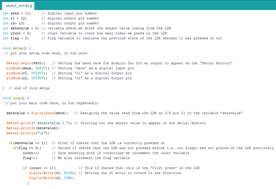

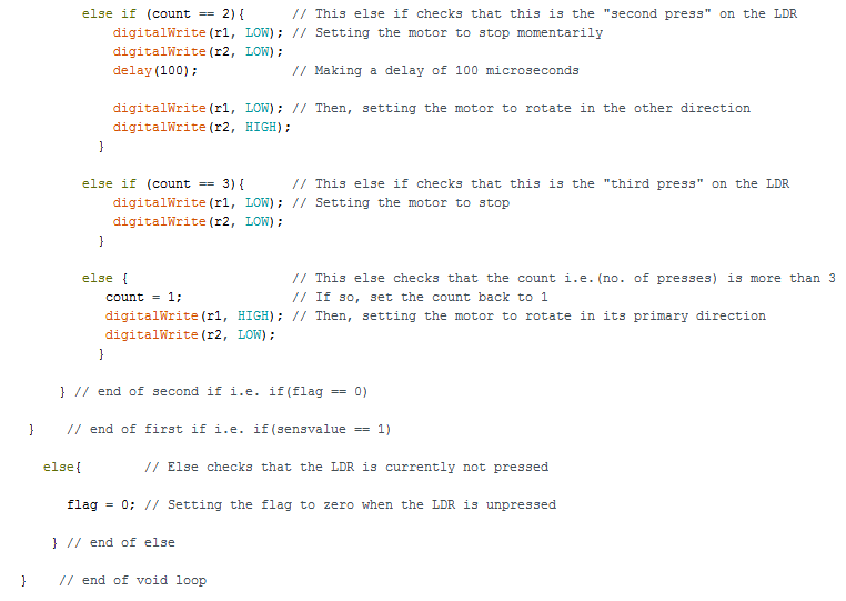
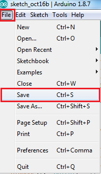
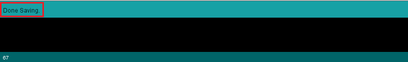
6. Save the code sketch by going to "File", select "Save", choose the directory that you want to save in and choose a file name, then press Save as shown in the figures below. (Note: Make sure that a "Done Saving." message appears near the bottom of the sketch's GUI as shown in the third figure.)


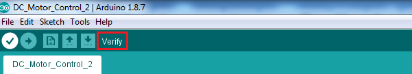
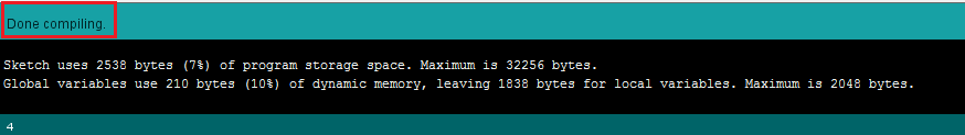
7. Now, it is time to compile/ verify the code to check for any errors that might be present. We go to the circular icon containing a check mark that is found in the toolbar at the top and click on it as shown in the first figure. The code begins compiling as shown in the second figure. And finally, make sure that this time a "Done compiling." message appears near the bottom of the sketch's GUI as shown in the third figure. (Note: If there is any syntax/ compilation error present it should appear in the black layout at the bottom and it will usually be written in an orange color and indicating the exact line of code where the error exists.)


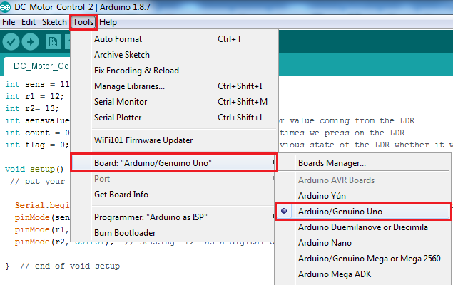
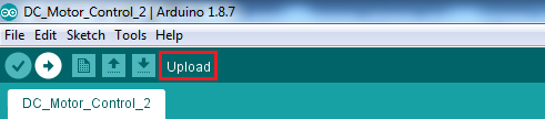
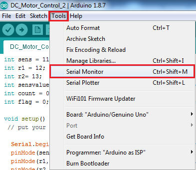
8. Finally, comes the time to upload our code into the Arduino Uno board so we connect the board to the PC using the USB cable and make sure that the computer reads the Arduino on a certain COM port. Then, we head to "Tools" to configure the board type that we are using along with the COM port that the Arduino is connected to, so in Tools we go to "Board:" and choose the board type to be "Arduino/ Genuino Uno" and at the same time we select the port to which the Arduino Uno is connected by going to "Port" and selecting the COM port as shown in the first and second figures respectively. To upload the code, we go to the circular icon containing a right arrow mark that is found in the toolbar at the top, directly to the right of the verify icon, and click on it as shown in the third figure. Again, make sure that a "Done uploading." message appears near the bottom of the sketch's GUI, as shown in the forth figure, to ensure that your code has been successfully uploaded on the Atmega chip. To see an output on the serial monitor, we also go to "Tools" and choose "Serial Monitor" as indicated in the fifth figure.


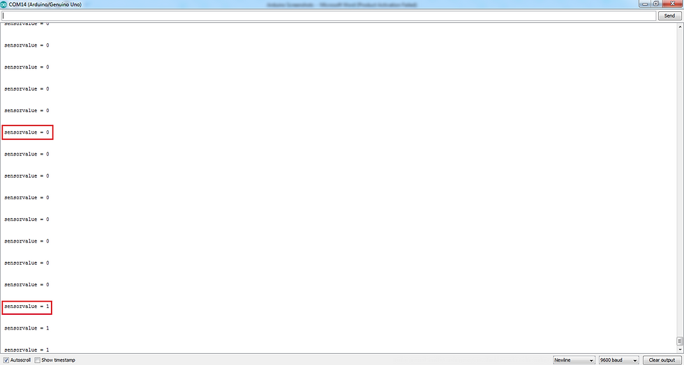
9. Here is the output that appears when opening the serial monitor, the sensor value is equal to 0 when the LDR is not pressed and equal to 1 when pressed as shown in the figure below.
c) Implementing the circuit in hardware:
Our final step was to implement the circuit in hardware, as shown in the figure below, and connect the Arduino Uno board to the PC to run our code and ensure that all the hardware is functioning properly.

Here is a video showing the circuit working and the DC motor rotating properly in both directions and stopping too:
Finally, here is a video of the same circuit and motor but with an additional 3D printed fan attached to the motor shaft that we made as an extra bonus to integrate between 3D printing, electronics, and programming as well.
Conclusion
In summary, this task was very informative and interesting as we got to work as a team to integrate between both electronics and programming and understand their fundamentals through practical work.


Comments