

Ball Construction Kit (Parametric design) Leaser Cutting
- Mohamed Khaled

- Nov 6, 2018
- 2 min read
Updated: Nov 13, 2018
This task is to design a parametric design construction kit and cut it in laser cutter, by using Autodesk Fusion 360 to design the kit then use RDCAM to print it on the Laser (Morn MT3050D) cutter.

What is Parametric Design?
Parametric design is a process based on algorithmic thinking that enables the expression of parameters and rules that, together, define, encode and clarify the relationship between design intent and design response, Parametric design is a paradigm in design where the relationship between elements is used to manipulate and inform the design of complex geometries and structures.
How To prepare the design to be cut on the Laser?
1. First thing we will do is to sketch the design on Autodesk Fusion 360.


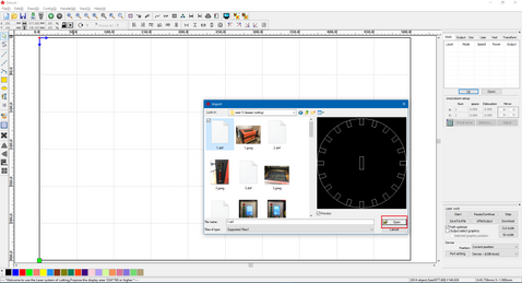
2.Then we will open the sketch on RDCAM to prepare it to be cut.

3. The first thing is to click Import in the toolbar to import your design.


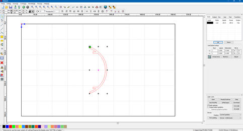
4. Now to can change the size of it as you like or you can copy it and past it as many as you like to fit your needs.

5. After finishing the design we will select the design and chose a layer color for it.

6. After choosing the layer double click on it to chose the speed and power of the cut/scan and chose weather you want to cut or scan.


7. Now we will save the design on USB to put it on the machine, by clicking SaveToUFile and save it in .rd extension.


Now after saving the design on the USB we insert it in the machine and cut.
How to use the Laser cutter to cut your design?

1. open the machine from the first switch in the right side of it.

2. Now insert the USB in its place above the power switch.
3. import the file from the USB.


4. Now we wait till the Laser finish cutting the design.
5. the result:

6. then i spray color it.

7. Now assembly it (before and after coloring).


Link:
https://drive.google.com/open?id=1VIRpzmUvk75Fr3WDRahz00XAFh9cqe7G


Comments